A ceramic capacitor is a fixed value capacitor where the ceramic material acts as the dielectric it is constructed of two or more alternating layers of ceramic and a metal layer acting as the electrodes the composition of the ceramic material defines the electrical behavior and therefore applications.
Ceramic capacitor markings polarity.
It leads to the condition that breaks the dielectric present in it.
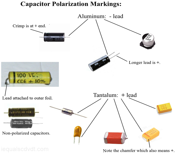
Additionally capacitors that are polarized they have a and a lead also carry a polarization marking.
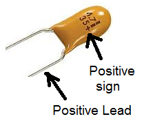
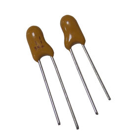
Tantalum capacitor polarity and markings these capacitors are known for their polarized behavior.
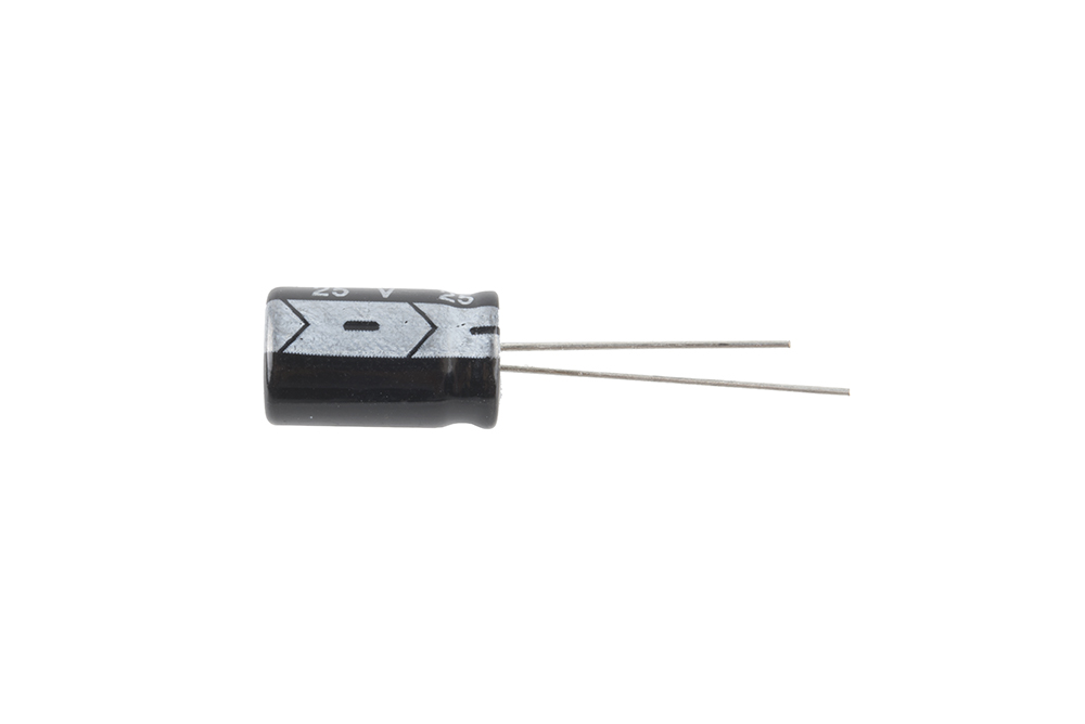
Traditionally this mark designates the end on an aluminum electrolytic capacitor which are usually shaped like tin cans.
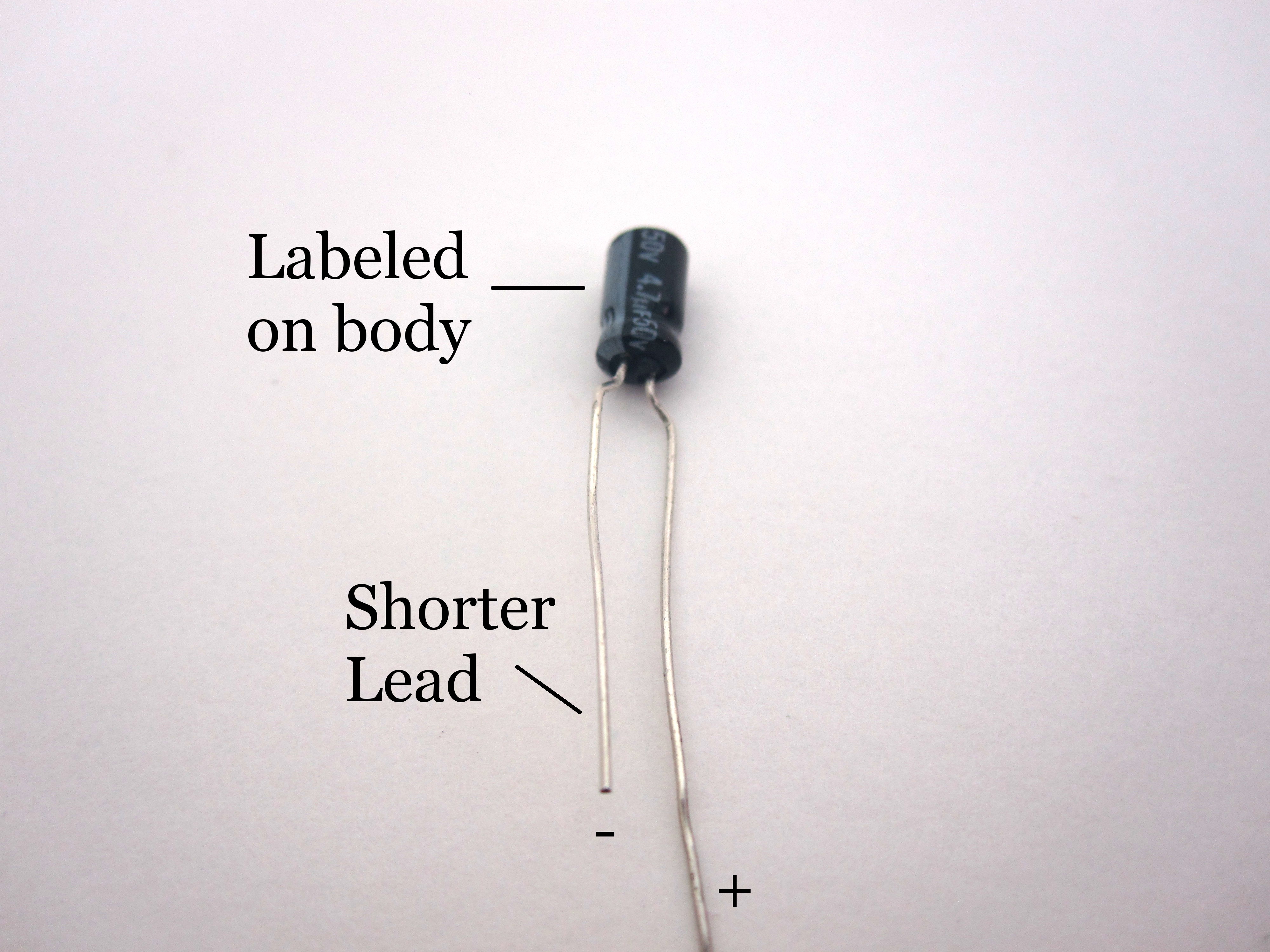
Polarity on the big capacitor.
How do you know the capacitor is nonpolar.
Some capacitors use a colored bar or a ring shaped depression to show polarity.
The tantalum capacitors only consist of the polarity markings.
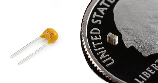
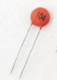
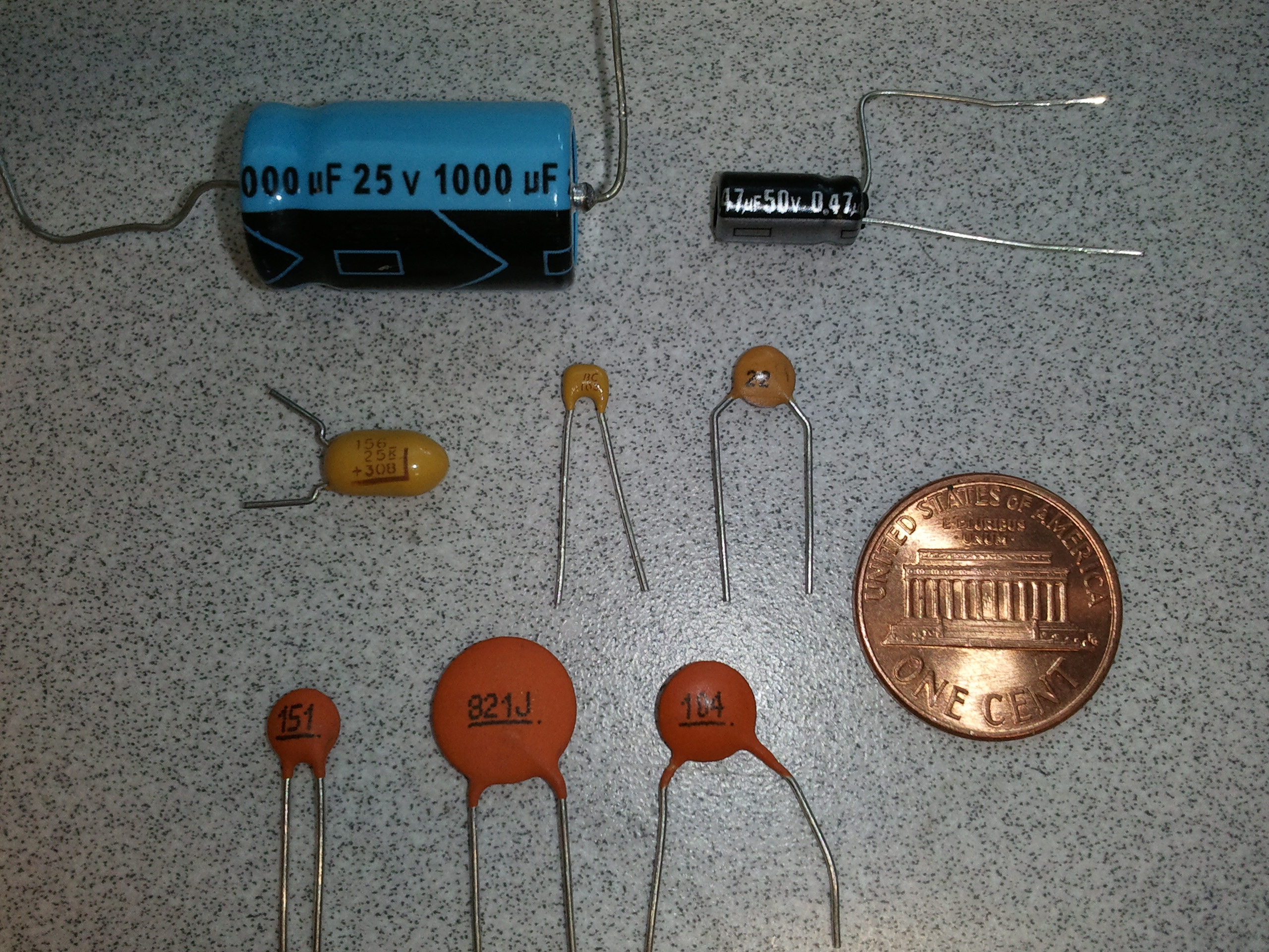
The above image shows a pair of ceramic disk capacitors labeled only as 10 and 15 these capacitors and all those under 1000pf directly show their capacitance in picofarads.
These are the most widely preferred capacitors because of its small sizes.
There is no negative indicator as this capacitor doesn t have a dedicated polarity and can be installed either way.
Only the capacitor made with aluminum as anode can be able to tolerate the voltages in reverse and these capacitors are unable to tolerate it.
On tantalum electrolytic capacitors which are very small this mark designates the end.
Capacitor polarity markings one important marking for polarised capacitors is the polarity.
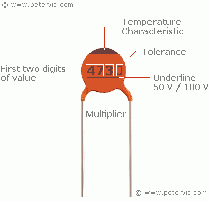
Understanding capacitor markings capacitors are routinely marked with at least their capacitance value.
Further when we require a capcaitor which has larger capacity to storage charges these ceramic ones are preferred.
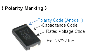
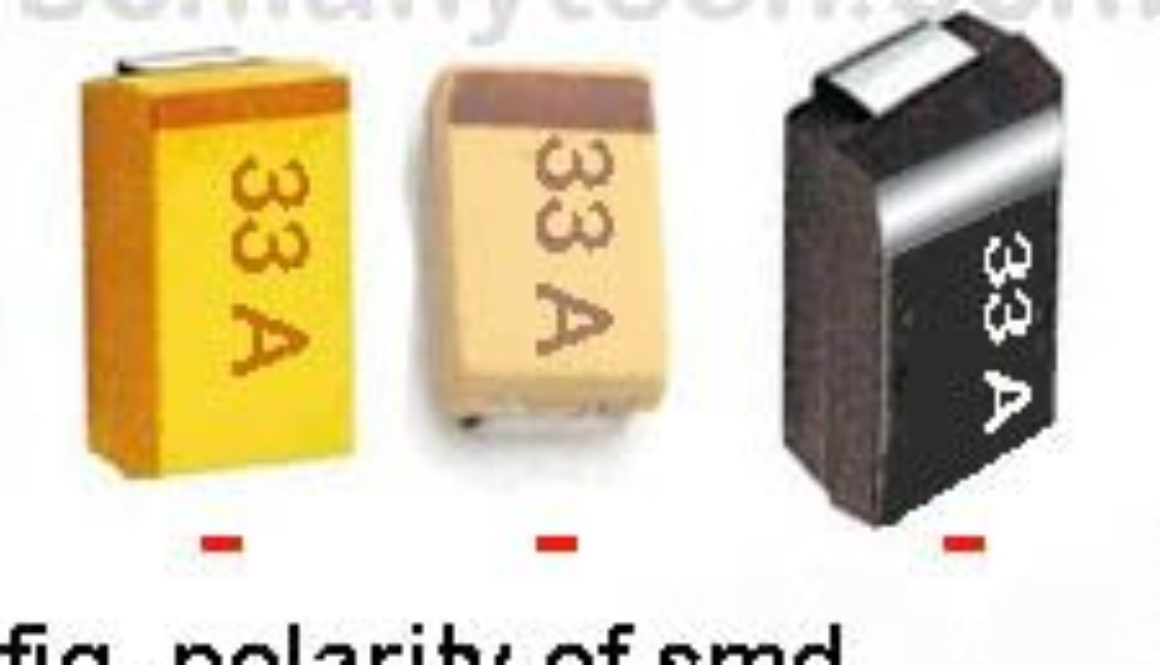
Markings of smd tantalum capacitor.
For axial leaded capacitors in which the leads come out of the opposite ends of the capacitor there may be an arrow that points to the negative end symbolizing the flow of charge.
Markings made on the capacitors help identify the polarity.
This is present in order to ensure the correct insertion of the capacitor in the circuit board.
This line bar indicates the positive terminal of the capacitors as shown in the figure above.
Note that on a rounded surface mount capacitor the small black corner indicates the negative side.
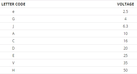
Many capacitors are also marked with value tolerance notation and a breakdown voltage.
The polarity of surface mount capacitors is marked by a white or black line at one of the ends of the device.
